Solutions
Mesh to CAD
Upload an STL or a 3D scan and get the part modelled back. Exact geometry as a STEP file, or native CAD you can open and edit in SolidWorks, Fusion 360 and FreeCAD.
The files
One shape, three kinds of file
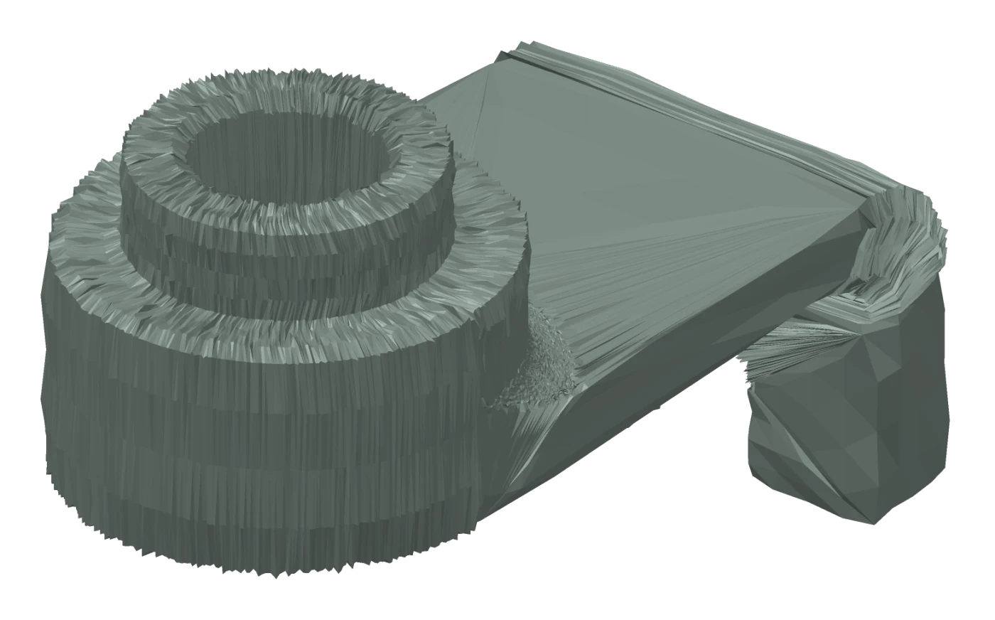
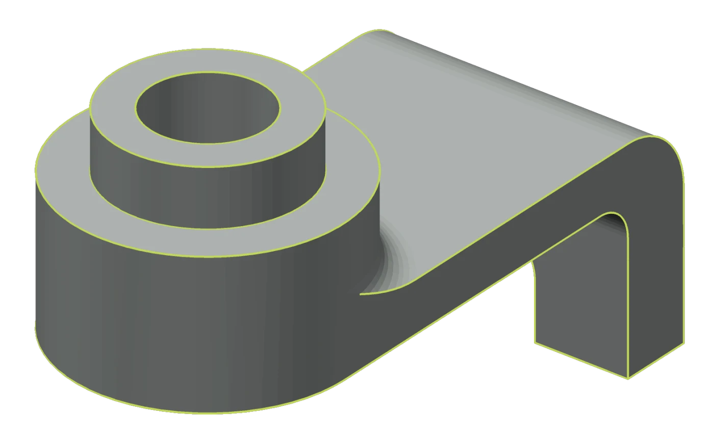
A converter hands back a solid made of the same triangles you uploaded. What decides whether the result is worth anything is not the extension on it, it is what the file can still do once it is open.
| You uploadSTL / mesh | You get backSTEP | You get backNative CAD | |
|---|---|---|---|
| What it holds | Thousands of flat triangles approximating a surface. | Exact geometry. Real planes, cylinders and radii. | The same exact geometry, plus the feature tree that built it. |
| Changing a dimension | There are no dimensions to change. | Direct editing only: push a face, resize a radius, cut a hole. | Open the operation, type the value, rebuild. |
| What it is for | 3D printing and visualisation. | Machining, quoting, inspection, exchange between CAD systems. | Design work, revisions, drawings, variants. |
The run
How it works
- 01Upload the mesh
Meshes (STL, OBJ, PLY) and point clouds straight off a scanner (E57, PTS), among others. No CAD file needed, which is the situation this exists for.
- 02Faber rebuilds the part
The agent reads the geometry and models it one feature at a time, then measures the result back against your scan. You can answer it while it works: comment on an edge or a face, say what is wrong there, and it reconstructs from your note.
- 03Open it in your CAD
Take the STEP file to machine, quote or inspect from, or the native CAD file to keep working on in SolidWorks, Fusion 360 or FreeCAD.
FAQ
Common questions
- What is the difference between an STL, a STEP file and a native CAD file?
- An STL holds a surface as thousands of flat triangles: an approximation, with no faces, no radii and no dimensions. A STEP file holds exact geometry, so a cylinder is a cylinder with a radius, which is what machining, quoting and inspection read. It carries no history, so there is no list of operations to go back and change. A native CAD file holds the same exact geometry plus the feature tree that built it, and that is the only one of the three where you edit a value and the part rebuilds.
- Can I edit what Faber gives me back?
- It depends which file you take. A STEP file can be modified through direct editing in any CAD system: move a face, change a radius, cut a new hole. What it cannot do is take you back to the operations the shape came from, because a STEP file does not store them. Export as native CAD instead and you get the feature tree, so you open the operation, change the value and the part rebuilds. That is available for SolidWorks, Fusion 360 and FreeCAD.
- What can I upload?
- Meshes such as STL, OBJ and PLY, and point clouds straight off a scanner such as E57 and PTS, among others.
- What happens if the agent gets a feature wrong?
- You comment on the geometry itself. Pick the edge or the face that is wrong, say what it should be, and the agent reconstructs from there instead of starting over.
- Does this work on a 3D scan?
- Yes. A scan reaches us as a mesh or a point cloud, and the reconstruction is measured back against it. Both bodies end up in the same coordinate frame, so the scan drops onto the model and either fits or does not.
- Which export should I take?
- Take STEP when the part is going straight to manufacturing or inspection: machining, CMM programming, quoting, or an assembly in another CAD system. Take native CAD when the part still has design work ahead of it and you want the feature tree to change values in.