Solutions
Drawing to CAD
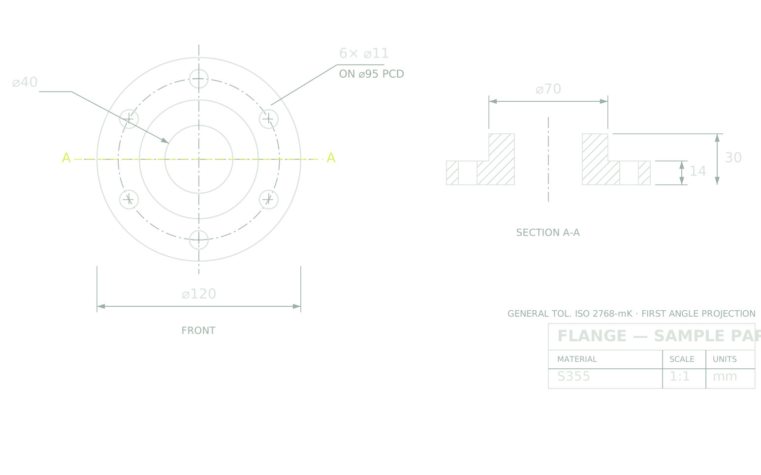
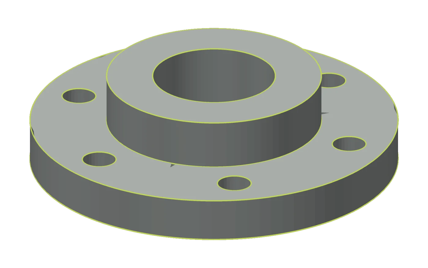
Upload a PDF, a DWG or a photograph of a technical drawing and get the part modelled in 3D. Exact geometry as a STEP file, or native CAD you can open and edit in SolidWorks, Fusion 360 and FreeCAD.
The files
From one sheet to a model
| You uploadThe drawing | You get backSTEP | You get backNative CAD | |
|---|---|---|---|
| What it holds | Views, dimensions, tolerances and notes. Everything but the solid. | Exact geometry. Real planes, cylinders and radii. | The same exact geometry, plus the feature tree that built it. |
| Reading a dimension | By eye, one at a time, and re-typed by hand into CAD. | Measured off the model. | Read from the operation that set it. |
| What it is for | Telling a supplier what to make, and inspection what to check. | Machining, quoting, inspection, exchange between CAD systems. | Design work, revisions, variants, a new drawing. |
The run
How it works
- 01Upload the drawing
PDF, DWG and DXF, or an image of the sheet (PNG, JPEG, TIFF), a photograph and a scan of a paper print included.
- 02Faber models the part
The agent reads the views, the dimensions and the notes, and builds the part one feature at a time. You can answer it while it works: comment on an edge or a face, say what is wrong there, and it reconstructs from your note.
- 03Open it in your CAD
Take the STEP file to machine, quote or inspect from, or the native CAD file to keep working on in SolidWorks, Fusion 360 or FreeCAD. The dimensions read off the sheet come with it.
FAQ
Common questions
- What can I upload?
- PDF, DWG and DXF, and images of a drawing: PNG, JPEG or TIFF, including a photograph or a scan of a paper print.
- Does it work on a scanned paper drawing?
- Yes. A scan or a photograph is read the same way a vector file is. It is the harder case, and it is the one that matters most on older parts, where the drawing is the only record left and no CAD file ever existed.
- What comes back?
- The part modelled in 3D, as a STEP file with exact geometry, or as native CAD for SolidWorks, Fusion 360 and FreeCAD, where you also get the feature tree and can change a value and rebuild.
- What happens to tolerances and notes?
- They belong to the drawing, not to the solid, and a STEP file has nowhere to put them. Faber reads them and hands them back beside the model as a table of dimensions, so nothing on the sheet is lost on the way to 3D.
- What if the model comes back wrong?
- You comment on the geometry itself. Pick the edge or the face that is wrong, say what it should be, and the agent reconstructs from there instead of starting over.
- Do I need every view?
- Give what you have. More views and more dimensions pin the part down further, and a drawing that leaves something ambiguous will leave the model ambiguous in the same place, which is where your comments come in.